
Flexible PCBs Can Be Used in Harsh Environments
Using flexible circuits allows for a reduction in assembly time as bulky wiring is not required. It also saves space and can decrease the weight of a final product, reducing production costs. In addition, they can accommodate complex geometries and are more reliable than rigid boards. They can also withstand mechanical stress and vibrations better.
Flex PCBs are made of a polymer material that is resistant to harsh chemicals, high temperatures and has better heat dissipation capabilities. They can also withstand a significant number of bending cycles without damaging the conducting circuitry. These factors make them a good choice for harsh environments, where environmental conditions are unpredictable and may cause damage to equipment or electronic components.
The base raw material for a flexible pcb is a flexible plastic known as polyimide. This is a very thin flexible film that has been coated with a network of epoxy resin. It is incredibly tough (you can’t tear it or noticeably stretch it by hand) and incredibly heat resistant, which makes it highly tolerant of the repeated solder reflow and thermal cycling that occur during product assembly and use. It is also relatively stable in expansion and contraction caused by temperature fluctuations, which is critical for a flex circuit.
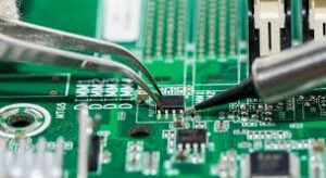
How Flexible PCBs Can Be Used in Harsh Environments
When designing a flex circuit, you can choose to implement any layer stack you want. However, the type of copper layer is a key factor when choosing the right design for your application. For example, solid copper layers offer better shielding but are less flexible, while cross-hatched copper layers are more flexible but may not provide as much shielding. The thickness of the copper layer is another important consideration. Thicker copper layers are more expensive but can reduce impedance.
To minimize the risk of failure, you should ensure your flex circuits meet IPC specifications and undergo rigorous testing. Testing can include thermal cycling, humidity, and accelerated life cycle testing to verify performance and reliability in harsh environments. It’s important to use proper soldering techniques, such as solder masking and reflow oven settings. Additionally, you should use an appropriate etch profile and drill-to-copper distance for your flex circuits.
For example, if you’re designing a flex circuit for repeated bending or movement, consider using a higher-grade rolled-annealed copper foil. This process elongates the grain structure and increases elasticity of the copper, which allows it to stretch more before fatigue cracking occurs. It can also help with etch yields for small traces and supports controlled impedance.
It’s also a good idea to use a surface finish that provides a solderable surface and protects the conductors from oxidation. You can choose from several types of surface finishes, including dry film, coverlay, and liquid photo-imaged polymer. Additionally, you should decide whether to use panel plating or pad-only plating (button plating). Panel plating is more common, but button plating offers superior flexibility as copper is deposited only on pads and vias. This also helps improve etch yields for small traces and allows for more consistent copper thickness, width, and spacing between tracks and holes.


