
thickness of a typical flexible printed circuit
The thickness of a typical flexible printed circuit (FPC) plays a crucial role in its performance, durability, and applicability in various electronic devices. Generally, the total thickness of an FPC can range from approximately 0.1 millimeters (mm) to about 0.5 mm, although custom specifications may vary depending on specific design requirements and applications. The thickness encompasses the substrate, conductive layers, and any additional coatings or laminates that may be applied to enhance functionality.
The substrate material is a primary contributor to the overall thickness of a flexible printed circuit. Common substrates used in FPC manufacturing include polyimide and polyester. Polyimide is favored for its superior thermal stability, chemical resistance, and mechanical properties, making it ideal for high-performance applications. It typically has a thickness ranging from 0.025 mm to 0.1 mm. Polyester, on the other hand, is a more cost-effective option but offers lower thermal performance and flexibility. The thickness of polyester substrates is generally similar to that of polyimide but can vary based on the intended application.
In addition to the substrate, the conductive layers, usually made of copper, also contribute to the overall thickness of the FPC. The thickness of the copper traces can significantly impact the circuit’s performance, including its conductivity and ability to handle current loads. Copper foil is commonly used in FPCs, with standard thicknesses ranging from 0.5 ounces per square foot (about 0.018 mm) to 3 ounces per square foot (approximately 0.105 mm). The specific thickness of copper used will depend on the electrical requirements of the circuit and the design specifications. Thicker copper layers can support higher current levels, while thinner layers can be used for low-power applications.
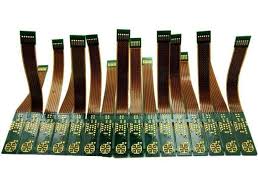
What is the thickness of a typical flexible printed circuit?
The thickness of an FPC can also be affected by additional layers or protective coatings. For example, a solder mask may be applied to protect the conductive traces and improve solderability. This mask can add a small amount of thickness, typically in the range of 0.01 mm to 0.03 mm. Additionally, flexible printed circuits may include various dielectric layers, which are used to insulate and separate the conductive paths. The choice of these additional materials can further influence the overall thickness of the circuit.
When designing a flexible printed circuit, engineers must carefully consider the balance between thickness, flexibility, and performance. A thicker FPC may offer enhanced durability and support for higher current loads, but it could sacrifice the circuit’s flexibility, making it less suitable for applications that require bending or conforming to complex shapes. Conversely, a thinner FPC may be more flexible and lightweight but may not be able to handle high currents or harsh environmental conditions effectively. Therefore, the design process often involves trade-offs based on the specific requirements of the application.
The thickness of a flexible printed circuit is also subject to industry standards and regulations. For example, the IPC-6013 standard provides guidelines for flexible circuits and outlines the acceptable thicknesses for various applications. Compliance with these standards ensures that FPCs meet reliability and performance expectations, particularly in critical industries such as aerospace, automotive, and medical devices.


