
Printed Circuit Board Prototype
The most common use of a printed circuit board prototype is to test the functionality of a new electronic design before going into a standard production run. It allows designers and their teams to make necessary adjustments and tailor the solution before committing to the full production order. Prototypes allow engineers to spot flaws and correct them quickly, preventing costly mistakes that can be made with full-spec production runs.
printed circuit board prototype also save time and resources by allowing for faster development and testing. While it may seem that prototyping adds several steps and costs to the process, prototypes serve important functions and create multiple advantages for both the designer, their team, and the client.
A prototype is a model that represents the layout and electrical connections of a Printed Circuit Board (PCB). It can be used to demonstrate the performance, appearance, and operation of a project. There are a variety of different types of prototypes, including breadboards, perf boards, stripboards, and CNC fabricated PCBs.
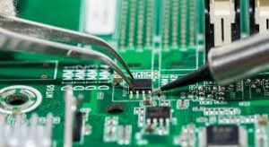
The Most Common Use of a Printed Circuit Board Prototype
The first step in making a prototype is to choose the material, and there are several options to consider, from solderable prototypes to high-end materials. The type of prototype chosen will depend on the intended end use and desired features of the final product. For example, a simple, functional prototype can be made with a single piece of breadboard, while a high-performance prototyping board requires a more permanent configuration.
Next, the circuit needs to be designed and arranged on the prototype board using a schematic and PCB layout software. The resulting files can then be used to fabricate the prototype PCB. These are called Gerber files, and they contain a detailed description of the layout and components, as well as the necessary drilling locations for holes. The drilled holes are then connected by copper strips that function as substitutes for wires.
Once the prototype is fabricated, the components can be placed and soldered on. It is recommended that the traces are cleaned and fluxed before soldering, to ensure a strong connection. The soldering process should be carefully monitored to ensure that the connections are secure and there is no damage to the copper.
After the component placement and wiring is complete, a functional prototype can be tested. It is important to test a prototype for any issues that may affect the finished product, such as signal flow, voltages, and current. If any errors are found, they can be corrected by re-routing the connections.
While it is possible to create a functional prototype with any type of prototype board, there are some additional benefits that come with using a CNC-fabricated PCB. These include better reliability and a more precise fit, which can reduce the chances of errors and improve the overall quality of the final product. Additionally, the PCB can be made with a wide range of components that would not be available in a breadboard or perf board. This gives the prototype a more accurate representation of what the final product will look like.

